DFG flow around cylinder benchmark 2D-3, fixed time interval (Re=100)
This benchmark simulates the time-periodic behaviour of a fluid in a pipe with a circular obstacle. It is set up in 2D with geometry data similar to the Re=20/Re=100 case.
Geometry and flow configuration
The underlying geometry is a pipe without a circular cylinder $\Omega=[0,2.2]\times [0,0.41] \setminus B_r(0.2,0.2)$ with $r=0.05$. Taking a fluid density of $\rho=1.0$, the fluid is characterised by the nonstationary Navier-Stokes equations
$$ u_t -\nu\Delta u + u\nabla u + \nabla p = 0,\qquad \text{div }u = 0 $$
with $u$ defining the velocity and $p$ the pressure. The kinematic viscosity is taken as
$$ \nu = 0.001. $$

Boundary conditions
For the lower and upper walls $\Gamma_1=[0,2.2]\times{0}$ and $\Gamma_1=[0,2.2]\times{0.41}$ as well as the boundary $S=\partial B_r(0.2,0.2)$, no-slip boundary conditions are defined,
$$ u_{|\Gamma_1} = u_{|\Gamma_3} = u_{|S} = 0. $$
On the \left edge $\Gamma_4={0}\times[0,0.41]$, a parabolic inflow profile is prescribed with a maximum velocity given by a sin-function,
$$ u(0,y) = \left( \frac{4 U y (0.41-y)}{0.41^2} , 0 \right), \qquad U=U(t)=1.5 \sin(\pi t / 8).$$
On the right edge $\Gamma_4={2.2}\times[0,0.41]$, do-nothing boundary conditions define the outflow,
$$ \nu \partial_\eta u - p \eta = 0 $$
with $\eta$ denoting the outer normal vector.
Reynolds number
For a maximum velocity of $U(4)=1.5$, the parabolic profile results in a mean velocity
$$ U_\text{mean} = \frac{2}{3}\cdot 1.5 = 1.0. $$
The characteristic length of the flow configuration is
$$ L = 2\cdot 0.05 = 0.1 $$
the diameter of the object perpendicular to the flow direction. This results in a Reynolds number
$$ \text{Re} = \frac{U_\text{mean} L}{\nu} = \frac{1.0 \cdot 0.1}{0.001} = 100. $$
Important numerical quantities
For the numerical comparison of data, the forces around the circle are measured. These drag and lift forces are defined by
$$ \begin{pmatrix} F_D F_L \end{pmatrix} = \int_{S} \sigma \eta ds $$
with $\eta$ denoting the outer normal vector of the circle. The stress tensor $\sigma$ in this formula is defined as
$$ \sigma := \nu \nabla u - p I. $$
A not so straightforward calculation which exploits $u_{|S}=0$ can be used to derive the following formulas for the drag and lift force, which can alternatively be used in 2D, see [2]:
$$ F_D = \int_S \left(\nu \frac{\partial u_{\tau}}{\partial_\eta} \eta_2 - p \eta_1 \right) ds,\quad F_L = - \int_S \left(\nu \frac{\partial u_{\tau}}{\partial_\eta} \eta_1 + p \eta_2 \right) ds $$
From the forces, one obtains the dimensionless drag and lift coefficients,
$$ C_D = \frac{2}{U_\text{mean}^2 L} F_D,\qquad C_L = \frac{2}{U_\text{mean}^2 L} F_L. $$
Setup of the test and data measurement
The simulation is carried out over a time interval $[t_0,t_1]=[0,8]$. At $t=0$, $u=(0,0)$ is taken as initial condition.
The following numerical quantities are measured:
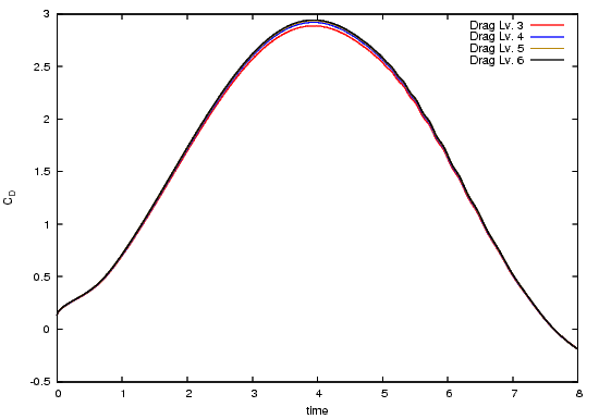
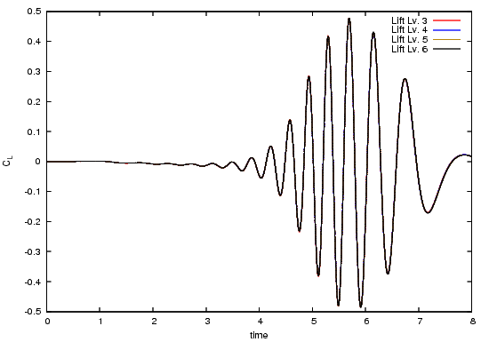
- The drag and lift coefficients $C_D$ and $C_L$ over the time interval $[t_0,t_1]$.
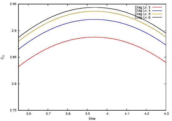
- $\max(C_D)$ and the time instant when this is reached,
- $\max(C_L)$ and the time instant when this is reached,
- the pressure difference $p_\text{diff}:=p(a_1)-p(a_2)$ in the points $a_1=(0.15,0.2)$ and $a_2=(0.25,0.2)$ on the front and rear side of the cylinder over the complete time interval $[t_0,t_1]$,
- the pressure difference $p_\text{diff}:=p(a_1)-p(a_2)$ in the points $a_1=(0.15,0.2)$ and $a_2=(0.25,0.2)$ on the front and rear side of the cylinder over at $t=8$,
with the amplitude amp=max-min and the mean value mean=(max+min)/2.
Test configuration
The test configuration used to generate the reference tests reads as follows:
- Finite element discretisation with $Q_2/P_1^\text{disc}$ in space. No stabilisation.
- Crank-Nicolson time discretisation scheme.
- Timestep: $k=1/1600$
- Regular refinement of the mesh shown below. For different refinement refinement levels, the following table shows the number of elements and degrees of freedom in the underlying system:
| Level | #Vertices | #Elements | #degrees of freedom |
|---|---|---|---|
| 1 | 156 | 130 | 702 |
| 2 | 572 | 520 | 2704 |
| 3 | 2184 | 2080 | 10608 |
| 4 | 8528 | 8320 | 42016 |
| 5 | 33696 | 33280 | 167232 |
| 6 | 133952 | 133120 | 667264 |

Exemplary Results
The first table shows information about max drag/lift coefficient values:
| Level | $\Delta t$ | $t(C_{D,\max})$ | $C_{D,\max}$ | $t(C_{L,\max})$ | $C_{L,\max}$ | $\Delta p(t=8)$ |
|---|---|---|---|---|---|---|
| 1 | 1/1600 | 3.8871875 | 2.3078383956 | 7.1228125 | 0.00473454189 | 0.13133949348 |
| 2 | 1/1600 | 3.9315625 | 2.8119800271 | 5.7328125 | 0.51118268011 | 0.10900361945 |
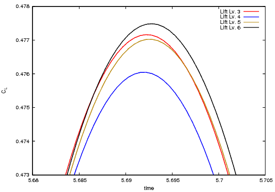
| 3 | 1/1600 | 3.9353125 | 2.8876944780 | 5.6921875 | 0.47716289896 | 0.11137208575 |
| 4 | 1/1600 | 3.9359375 | 2.9210042217 | 5.6921875 | 0.47604534419 | 0.11142907055 |
| 5 | 1/1600 | 3.9359375 | 2.9364004145 | 5.6928125 | 0.47702397570 | 0.11151270802 |
| 6 | 1/1600 | 3.9365625 | 2.9437637214 | 5.6928125 | 0.47748781595 | 0.11154138872 |
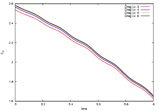
The following pictures shows the drag coefficient over time, for the complete time interval, zoomed to $[3.55,4.3]\times[2.75,2.95]$ and zoomed to $[5,6]\times[1.6,2.6]$.
The following pictures shows the lift coefficient over time, for the complete time interval and zoomed to $[5.68,6.705]\times[0.473,0.478]$.
Reference results
From the following table, the underlying GNUPLOT data can be downloaded. The files provide the data for different refinement levels in space.
| Description | GNUPLOT-file |
|---|---|
| Drag/Lift, $\tilde Q_2/P_1^\text{disc}$ | draglift_q2_cn_lv1-6_dt4.zip |
| Pressure, $\tilde Q_2/P_1^\text{disc}$ | pressure_q2_cn_lv1-6_dt4.zip |
| GNUplot command file | plot_bench3.plt |
References
| Id | Title |
|---|---|
| [1] | Turek, Schaefer; Benchmark computations of laminar flow around cylinder; in Flow Simulation with High-Performance Computers II, Notes on Numerical Fluid Mechanics 52, 547-566, Vieweg 1996 |
| [2] | John; Higher order Finite element methods and multigrid solvers in a benchmark problem for the 3D Navier-Stokes equations; Int. J. Numer. Meth. Fluids 2002; 40: 775-798 (DOI: 10.1002/ d.377) |
| [3] | John; Reference values for drag and lift of a two-dimensional time-dependent flow around a cylinder; Int. J. Numer. Meth. Fluids 2004; 44: 777u2013788 (DOI: 10.1002/ d.679) |
